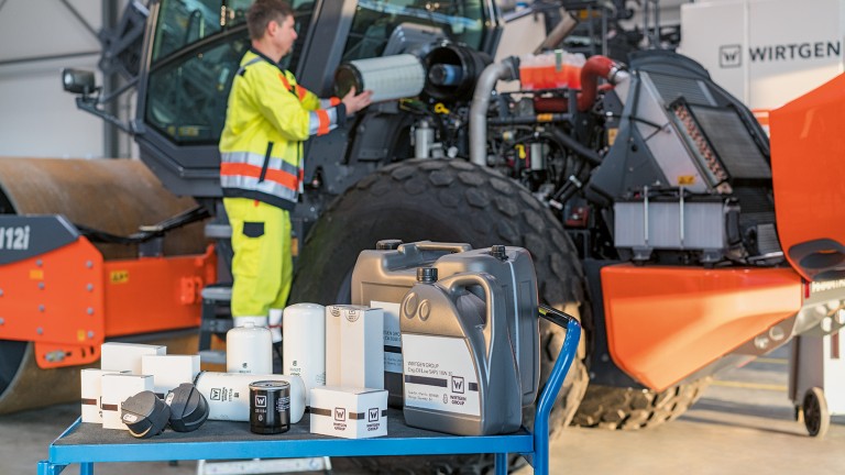
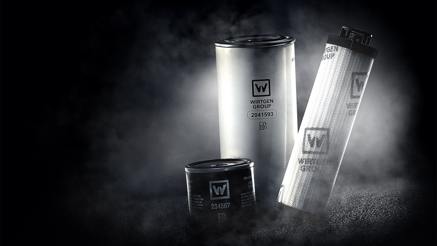
Wirtgen Group filter types

Air filters

The reliability of combustion engines depends on a supply of clean air, oil, and fuel. There are three separate systems for providing these three essentials, each of which needs its own filter system.

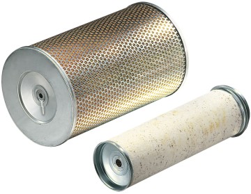
Air filters clean the air required for combustion and thereby minimise the risk of damage to engine components. To prevent damage, all filters only allow dirt particles up to a certain particle size in the micrometre (µm) range to pass through it. The exact particle size depends on the engine. As a rule, WIRTGEN GROUP machines are fitted with upstream pre-filters that reduce the load on the actual air filter.

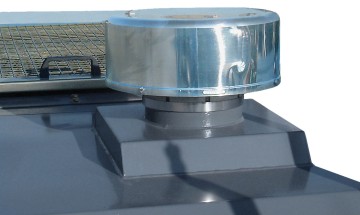
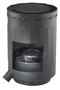
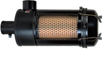
The amount of air required by the engine is a decisive factor when choosing the right pre-filter. Two different upstream system options are presented here, both of which serve the same purpose within the system. Air pre-filters with an impeller and cyclone air pre-filters.


Air pre-filters with an impeller

A rotor (impeller) is driven by the intake air drawn into the combustion engine. The high speed of the impeller subjects dirt particles to very high centrifugal forces and, as a result, even the smallest particles are ejected through a dust discharge valve in the housing.

Cyclone air pre-filters

This type of pre-filter creates a vortex in the intake air and removes the coarsest contaminants by centrifugal force.

How the cyclone air pre-filter works

Outlet unit for vortex energy recovery
Cyclone chamber
Inlet guide vanes for vortex generation
Contaminated intake air
Dust discharge
Pre-filtered air to main air filter

Attached to the main filter by metal clips, the dust collector facilitates regular emptying and cleaning. Thanks to its pleated structure, the main air filter is extremely robust. This effectively prevents the pleats sticking together under unfavourable conditions. The filter is securely fixed in the valve seat by an axial tensioning rod welded into the housing. The efficiency of the main air filter depends primarily on how long it has been in use.

Changing the air filter cartridge too soon means that it will not be able to achieve optimum efficiency. The high-quality filters used in WIRTGEN GROUP machines achieve their highest efficiency after about 10 to 15% of their potential operating time. A filter should therefore be replaced only when it has been cleaned several times and after the underpressure signal appears.

The secondary filter is a safety element made of a non-woven fabric that provides considerable safety reserves in the event of even the smallest pressure losses. The now sufficiently cleaned air is drawn into the combustion engine only after it has passed through this element.

The combustion air is therefore passed through a total of up to four filtering components including the pre-filter. The effort invested here pays off, especially when we consider that WIRTGEN GROUP machines need to function faultlessly on various dusty construction sites around the globe – which demands that each and every one of these elements must be able to fulfil its tasks with above-average reliability and efficiency.

Engine oil filters

For precisely this reason, the engine oil that lubricates and cleans engine components such as the valves and pistons must also be reliably cleaned. Severely contaminated oil can seriously damage the engine. The engine oil filter makes it possible to extend the service life of both the engine oil itself and the engine.

Bypass valve
Filter element
Filter housing
Centre tube
Non-return valve on clean side
Non-return valve on unfiltered side
Seal
Fuel pre-filters

Water separator and fuel filter

In view of new engine technologies and increasingly stringent emission standards, the need for cleaner fuel is becoming more and more important. The flowchart shows the schematic layout. The water separator is often integrated in the fuel pre-filter.

Engine oil and fuel system

Engine oil
Engine oil filters
Engine
Fuel
Fuel pre-filter
Fuel main filter
Injection pump
Hydraulic oil filters

The filter types used in hydraulic systems are differentiated by their location and purpose within the system. The various demands on hydraulic filters are reflected by the differences in their construction. In the following, we describe the most commonly used filter types:

Suction filters

The purpose of a suction filter is to protect the hydraulic pump against coarse contaminants in the hydraulic fluid that can quickly lead to sudden pump failures. Due to the high risk of cavitation – bubbles of steam caused by low pressure peaks and subsequent damage in the micrometre (μm) range – in the pump, relatively coarse filter material with a filter rating of 25 μm is used. In view of this, suction filters are unsuitable for ensuring the protection of the system components required for efficient functioning of the system. In addition to the risk of cavitation, poorer cold-start behaviour is another reason for replacing this type of filter with a more modern combined return/suction filter or an in-line pressure filter.

Pressure filter
Hydraulic tank
Hydraulic pump
Pressure filter
Valve
Hydraulic cylinder
Return filter

The in-line pressure filter is installed directly after the system pump (e.g. hydraulic cylinder pump; open loop). It should always be fitted with a contamination indicator. This filter type is specifically designed for the system pressure and volume flow. One of its main purposes is the protection of sensitive components (e.g. servo valves). Pressure filters not only have to withstand the maximum pressure in the system, but also have to absorb pressure peaks over a long period of time.

Only line filters without a bypass valve should be used before highly sensitive hydraulic components. Here, the filter element must be able to withstand extreme differential pressure loads. Consequently, it goes without saying that the filter housing must be designed to withstand the maximum dynamic system pressure.

Return filter

The return filter is installed in the return line. When installed as an in-line filter, a tank-mounted filter, or an integrated in-tank filter, it filters the hydraulic fluid in the system as it is returned to the tank. The maximum possible volume flow is a decisive factor in the choice of the right filter. This corresponds to the area ratio of the piston to the piston rod of the hydraulic cylinder, and can be greater than the volume flow generated by the pump.

Foaming of the fluid in the tank always occurs when the fluid outlet from the filter is above the fluid level (always keep an eye on the level of the hydraulic oil in the tank). In view of this, care must be taken to ensure that the outlet is always below the surface of the fluid under all operating conditions. This can be achieved by a pipe (tube) or a volume flow diffuser in the filter outlet.

Breather filters

Temperature variations and the use of cylinders or hydraulic accumulators cause fluctuations of the fluid level in the tanks of hydraulic systems. The resulting pressure difference between the tank and the surroundings has to be compensated for by an exchange of air. When this happens, it is possible that dirt in the intake air may be drawn into the tank. To ensure that breather filters can prevent this effectively, they should have the same filter rating as the system filters used in the hydraulic loop.

In-line pressure filters

The in-line pressure filter is connected directly to the outlet of the feed pump. It filters the required hydraulic oil before it is pumped into the closed hydraulic loop. This ensures that the hydraulic system is always supplied with the required quantity of oil. The in-line pressure filter is often also fitted with a contamination indicator.

Combined filter (return/suction filter)
Tank
Cylinder
4/3-way valve
Adjustable hydraulic pump
Adjustable hydraulic motor
Hydraulic pump with one pumping direction
Combustion engine
Radiator with bypass
Combined filter (return/suction filter)
Breather filters

In the case of mobile equipment with working hydraulics (hydraulic cylinders) and travel hydraulics, combined filters (return/suction filters) are used. are used. This filter type offers the advantage that filtered oil is supplied to the feed pump of the travel drive (item 6 in the diagram) at a positive pressure of approx. 0.5 bar.This reduces the risk of cavitation in the pump and enables excellent cold-start properties.

In order to maintain the pre-load pressure of approx. 0.5 bar at the connection to the feed pump, it is essential that a positive pressure difference of at least 10% between the return flow and suction volumes is maintained under all operating conditions. A pressure relief valve (V2 in the diagram) returns the hydraulic fluid directly to the tank when the pressure difference exceeds 2.5 bar (no bypass to the closed system).

If the leakage oil from the hydrostatic drive is routed through the filter in addition to the oil quantity in the open loop, care must be taken to ensure that the permissible leakage oil pressure is not exceeded (taking the pressure increase in the leak oil line, the oil cooler, and the pressure relief valve into account) in order to protect the radial shaft sealing rings.

The hydraulic filters presented here are used for different purposes at the individual brand headquarters of the WIRTGEN GROUP. Preferably, filter types should be used that are most suitable for the application purpose of the machine.

Would you like to quickly and easily order your WIRTGEN GROUP filter sets and maintenance packages now?

Select your brand and find what you need to order with just a couple of clicks:

WIRTGEN GROUP maintenance parts
Back to Overview