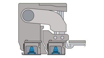
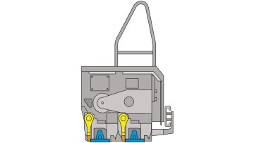
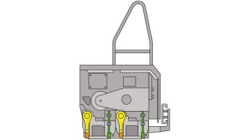
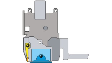
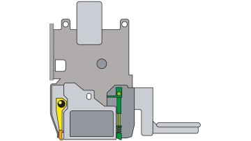
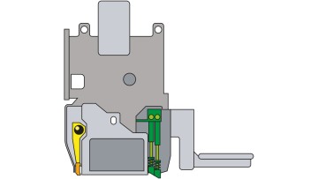
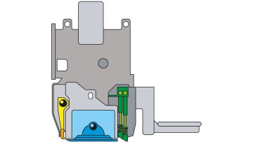
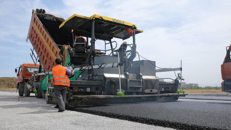
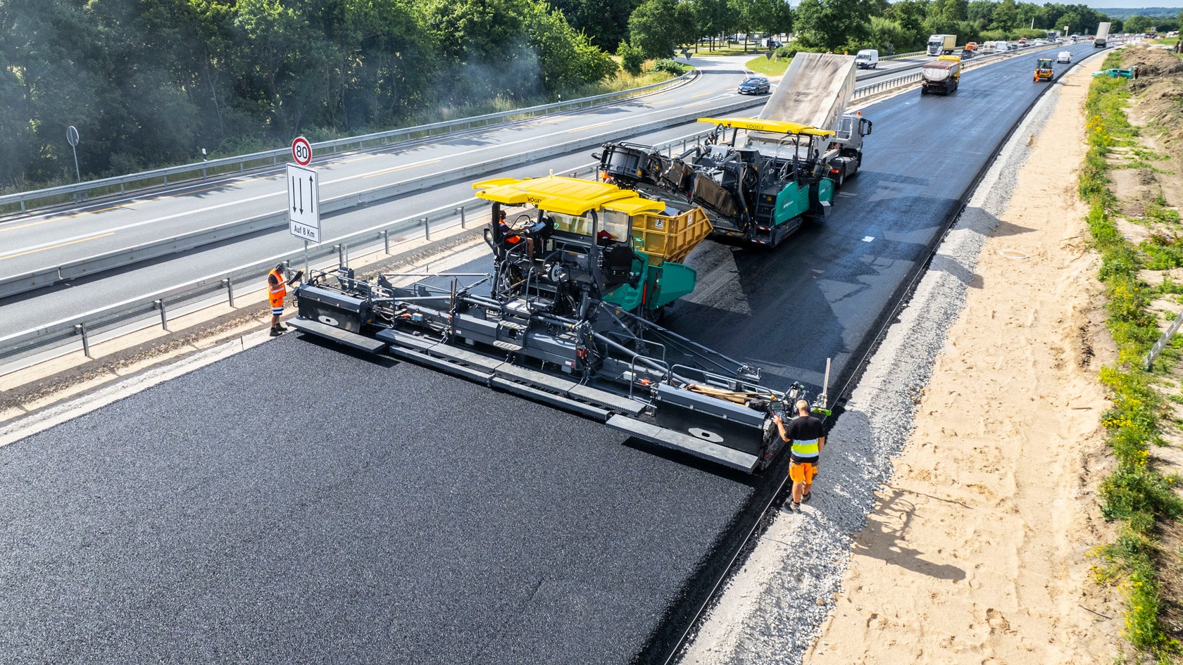
The aim of the screed's compacting systems is to achieve the greatest possible pre-compaction so that different layer thicknesses have less influence on the amount of rolling required for final compaction. VÖGELE employs the compacting systems listed below:
Applications
V and TV screeds can be used for all conventional mixes that are easier to compact. Less final compaction effort is necessary when TP1 and TP2 screeds are used. The two variants differ with regard to the compaction values that can be achieved; whereby all conventional mixes can be processed. The TP2 variant delivers a high level of pre-compaction, particularly in the case of thicker paved layers.
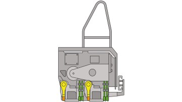
TVP2 screeds can be used for paving with all conventional mixes. This variant is also suitable for paving PCC (Paver Compacted Concrete), as surfaces paved using this method require no final compaction. The TP2 Plus variant offers even higher compaction values and is used in the VÖGELE InLine Pave train for the production of the binder course. Due to the immediately following paver, this layer must already have final compaction values. All compacting systems on VÖGELE screeds - tampers, vibrators and pressure bars - are independently controlled and can be switched on or off as required.
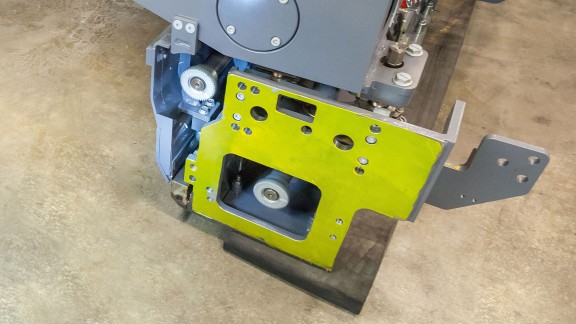
Compaction aggregates of extending screeds
Compaction aggregates of fixed-width screeds
The interaction of the tamper, the base of the screed (screed plate), bevel iron, side plate ski and pressure bar ensures that the mix is held in place as a package that counteracts material spreading in any direction. The end-result is an almost finally compacted asphalt package.
The downward vertical stroke of the tamper presses the mix to be paved under the base of the screed. It ensures a regulated feed of material to the screed and achieves the required degree of pre-compaction.
The materials from which the tamper is constructed must fulfil particularly high standards due to the continuous impact loads from its vertical reciprocating motion. A hard surface and a ductile core are among the most important properties of tamper bars. At the beginning of the manufacturing process, profile rods are cut to the required length for the tamper bars with a CNC-controlled saw. Thanks to the chamfered leading edge, the tampers ensure even mix feed and optimal compaction in later use. The service life of these components depends on their hardness. Induction hardening, the process also used for the pressure bars, ensures consistent hardness over the entire length of the bar and achieves a hardening depth of at least 5 mm. The core remains ductile and flexible, while the surface, which is in constant contact with the mix to be compacted, retains its high resistance to wear. The bores for the heating rods are drilled on a CNC deep hole drilling machine developed especially for VÖGELE. In these this bores, the heating rods heat the bars (tamper bars and pressure bars) centrally from the inside over the entire length and guarantee homogeneous heating. In this way, bitumen residues are prevented from adhering during subsequent paving (particularly during the pre-heating phase prior to starting work) and abrasive wear on contact surfaces is reduced.
In the final step this phase, all bars are straightened in a straightening jig. The maximum permissible flatness deviation is 0.5 mm.
The wear-resistant steel used in the manufacturing of screed plates combines properties such as ductility and fracture strength. In view of the sliding friction that takes place between the screed plate and the paving mix, these particular properties play a decisive role in maximising the service life of these components.
During the manufacturing process, the raw material for the screed plates is first laser-cut to the required dimensions. A chamfer that assures good material feed behind the tamper bar is milled off the later underside of the front screed plate in the direction of travel. To prevent cold welding between the back of the tamper and the leading edge of the screed plate (in the forward direction of travel), this area is also correspondingly machined. This optimisation ensures precise tamper bar guidance and also significantly increases the service life of both components. Following stress-relieved straightening to ensure evenness, the threaded bolts are welded onto the upper surface by a CNC-controlled stud welding machine. On average, 25 threaded bolts with maximum tensile and shear strength are welded to each screed plate.
In operation, the pressure bars powered by single or double pulsed-flow hydraulics (TP1 or TP2 variants) are subjected to similar loads as the tamper bars.
All high compaction screeds from VÖGELE are equipped with pressure bars. They are located immediately behind the screed plates and perform the final phase of compaction by the screed. The positioning of the pressure bars at the end of the screed has the advantage that the compaction effect can be regulated independent of the material feed and pre-compaction. If the profile of the pressure bars is already too heavily worn, the compaction results will be well below the values stipulated by the client. The manufacturing processes for pressure bars and tamper bars are very similar, except that there are two different types of pressure bars:
Pressure bar 1, immediately behind the screed plate, has a uniformly bevelled profile. The rearmost third of pressure bar 2, which follows, is flattened. TP1 screeds have only type 2 pressure bars.
VÖGELE leads the field when it comes to electric screed heating. As early as 1952 VÖGELE was the first road paver manufacturer to use this highly efficient, eco-friendly design and, to the present day, continues to shape the development of screed heating with numerous innovations. All compacting systems are heated across the full screed width to maximise compaction performance and assure the delivery of a faultless and uniformly sealed surface texture. This effectively prevents the adhesion of mix and provides the ideal operating temperature for the floating behaviour of the screed. Tamper and pressure bars are heated evenly from the inside by integrated heating rods. Screed plates are fitted with a heating rod as a standard feature that distributes heat across the entire plate surface. As a further option, the bevel irons and the side plate skis can also be fitted with heating elements.
Heating rods
On all VÖGELE road pavers, powerful and robust three-phase A.C. generators supply the screed heating with the energy it needs. Smart generator management ensures that they work with optimal efficiency. It ensures that sufficient generator power is available for the current paving width, independent of the engine speed. Power reserves are available in full for paving.
3-point suspension
The 3-point suspension for VÖGELE extending screeds comprises the following components: the telescoping tube, the hydraulic cylinders in conjunction with the guide tube, and the torque restraint system. The ErgoPlus console controls two hydraulic cylinders that precisely set the width of the extending screed. The generously dimensioned telescoping tube keeps the extension units securely in position. At full screed extension the three concentric tubes that make up the telescoping tube remain supported by at least one half. Due to the large bearing span, this reliably counteracts the vertical uplift forces. The smooth movement of the telescoping tubes, without jamming or tilting, is an important prerequisite for faultless project execution – particularly when frequently changing paving widths are required. The slide tapes inside the tubes guarantee freedom from play and ensure jerk-free movement when being extended and retracted. VÖGELE achieves width variability while retaining high stability by using an additional guide tube. This tube, which is connected to the extending unit via a linear sliding bearing, enables precise, parallel adjustment of the width of the screed up to even the largest paving widths. The screed's extension units are subjected to enormous material pressure in the horizontal plane, which results in a torque force.
This torque force is counteracted by bracing, the torque restraint system, that stops the extension unit twisting or turning around the telescoping tube.
The telescoping tubes provide the extending screeds with the necessary stability (system stiffness) and ensure maximum precision (freedom of the system from play) during extension and retraction. While the stiffness is determined above all by the large tube diameter, the extremely precise concentric fit of the inner and outer tubes is crucial factor in ensuring freedom from play. Due to the precision engineering required in the production of the telescoping tubes, they are manufactured in an elaborate process with several phases. After the machining processes, the elements are passed on to a series of honing and grinding processes to guarantee an absolute minimum amount of play in the concentric fit. On the honing machine, the inner surfaces of the telescoping tubes are finely honed to achieve a high-precision surface finish with a maximum roughness depth of 0.005 millimetres.
In comparison, the diameter of a human hair is approximately 0.1 mm.
To achieve a hard and corrosion-resistant surface, the outer surfaces are first polished, painstakingly cleaned and then electroless nickel plating according to the Kanigen® process. The telescoping tubes from VÖGELE are manufactured exclusively as sets in a single process. This safeguards their characteristic properties of stability and precision and guarantees the consistently high paving quality clients expect.
Guide strips and sliding blocks are parts of the VÖGELE torque restraint system. The guide strip is attached to the screed body of the extension units by screws. A special locking compound is applied to the roughened underside of the screws. This counteracts the loosening of the screws due to the continuous vibration of the screed. The sliding blocks are mounted on the outer extension units of the extending screed. One sliding block is located above, and the other below the guide bar.
The bottom sliding block is securely bolted down attached, while the other is mounted in such a way that it can be adjusted without any problems in the event of wear via an eccentric mounting This configuration ensures safe and secure guidance of the extension units and high stiffness of the overall screed system.
All elements of the screeds, and especially those that are directly involved in the compaction process (tamper bars, screed plates and pressure bars), are subject to varying degrees of material-dependent wear. There are many different reasons for this. Although wear can be delayed to a certain extent, it can nevertheless not be avoided. Fouling, incorrect assembly or poorly-fitting parts from third-party providers affect not only productivity and/or pavement quality, but can also increase wear on other components.
Among the most common reasons for unusually short component service life are:
What exactly is wear?
Wear is caused by the pressure between two elements in contact (e.g. between the mix being paved and the screed plate) when the elements move relative to one another. In such cases, friction detaches small particles from the surfaces of both elements.
How can wear be avoided or prevented?
Fouling increases wear: abrasive materials grind material away at all points of contact and drastically shorten the service life of components. Regular maintenance and cleaning is essential for maximising the service life of components.
A general distinction can be made between external and internal factors.
Here, external factors are those defined by the material to be placed, the tonnage per hour or specific on-site requirements.
Internal factors are generally incorrect settings on the screed or the consequences of inadequate cleaning.
The planing angle of the screed plays an essential role when paving the asphalt mix. This angle is set by the tow point (aka pull point) on the paver's screed levelling arm. Apart from its response to the adjustment of the height of the screed tow point, the positioning of the screed is also influenced by changes in the advance speed of the paver and the various properties of the mix to be compacted. The paving thickness should be checked after the start of paving to determine the ideal position of the towing shackle mount and, in turn, the resulting screed planing angle. The angle can be positive or negative (refer to the graphics). A slightly positive planing angle is of advantage for the paving quality and quantity. A further benefit is the minimisation of application-related wear.
The greater the paving thickness (layer thickness), the larger the screed planing angle should be. The more material in front of the screed, the greater the uplift of the screed, which, in turn, also influences the screed planing angle.
If the positive screed planing angle is too large, it will cause increased wear on the screed plates and irregularities on the paved surface. A negative screed planing angle, caused when the tamper speed is too high or when the stroke of the tamper bars is too long, produces small, regularly occurring irregularities. When correctly set, with a slightly positive screed planing angle, the entire underside of the screed plate is used to smooth the surface of the pavement.
All screed plates of an extending screed should be set to the same screed planing angle to ensure that different paving widths do not degrade the floating behaviour of the screed. For this purpose, the leading edge of the screed plate of the screed extensions should be set approximately 0.5-1 mm higher than the rear edge when setting up the screed.
The tamper is the decisive compacting system when the key concern is the minimisation of wear on components such as the screed plate or pressure bars. This means that if the tamper is heavily worn, wear on the screed plate and pressure bars is already on the way. If increased wear is found in the central section of the tamper, the cause is generally a deformed (twisted) bar. The bar should be checked to ensure it is straight and replaced if necessary. In the event of an incorrect setting for the height of the extension units, or when the screed is incompletely extended, increased wear can occur on the part of the tamper bar behind the basic screed. The ‘freely moving’ section of the tamper bar wears more slowly, as here the material has not yet been compacted by the basic screed and is ‘softer’ than the material already compacted behind the basic screed.
Unusually high wear occurs on the outer edges of the tamper bars if overlapping ‘hot-on-cold’ paving is frequently undertaken. In such cases, the tamper bars compact already compacted pavement over a length of approx. 3-4 cm.
The effect of tamper wear on the floating behaviour of the screed
The shape of the tamper affects the floating behaviour of the screed. If the tamper is sharply pointed, the entire screed system loses its pre-compaction effect and the rear edge drops. As a result of this, the screed develops a much too large planing angle. This causes the screed to react strongly during paving, produces an uneven pavement surface and significantly increase wear on all other components.
In the case of sharply pointed tamper bars, all bars on the screed should be removed and replaced as a set.
If the screed plate is heavily worn with wedge-shaped wear at the rear, this indicates that the screed planing angle has been continually too large and, in consequence, the pre-compaction under the screed has been too low.
The cause of this is generally found to be a permanently too low setting of the tamper speed. There is often heavy wear on the leading edge of the screed plate caused by an excessively high clamping force exerted by the metering gate that is transferred through the tamper to the leading edge of the screed plate. If shadowing occurs in the pavement surface, in the majority of cases partial erosion of the screed plate is the cause. Such erosion is due to heavy, partial wear (e. g. during compensation for unevenness) in combination with strong thermal impact.
In the case of screed plates with through stud bolts (non-original VÖGELE screed plates), partial erosion occurs almost always around the bolts on the underside of the screed plate. This erosion is due to the different wear behaviour of the bolt and screed plate materials.