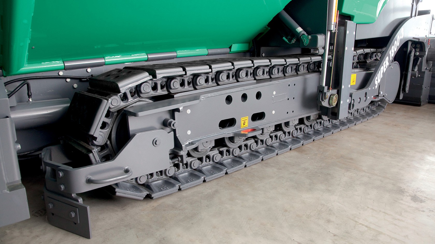
Among the most frequent reasons for undesirable wear are:
Increasing service life means:
Leakage is the reason generally given to justify the premature replacement of track rollers.
However, a distinction must be made between leakage and untightness.
Due to the sliding bearing seal, the leakage of small amounts of oil is perfectly normal and, in industry jargon, is commonly referred to as ‘sweating’. This absolutely typical occurrence in the case of sliding bearing seals cleans the lapped surfaces of the sliding rings and prevents the ingress of dirt into the roller or sliding bearings in the track roller.
Track rollers with leaking or seized bearings should be replaced as soon as possible to avoid damage or wear to other track unit components, e.g. the track chain. This because the blocked rotation of track rollers can lead to rapid wear on the track chains, as it increases the frictional forces on the track roller casing and the contact surfaces of the chain links. At the same time, a pressure increase in the hydraulic system of the advance drive will be observed, since the necessary energy to propel the track unit increases. High loadings will also occur on other mechanical components, such as for example, on the tooth flanks of the drive gear or the bushes that protect the chain bolts.
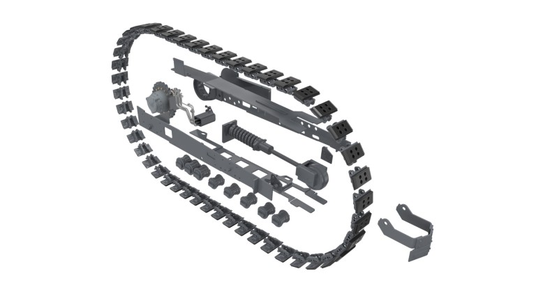
If the diameter of the track roller contact surfaces is smaller than wear dimension A (see the table) wear can occur on the outer edges of the chain which as a result allow the bolts of the track chain to wear. In addition, the bearings of the idler guide and the drive gearbox on the drive sprocket will be too heavily loaded by a high machine weight, since track rollers with a reduced diameter will no longer be able to safely absorb the vertically applied forces.
Machine type | Size: Diameter | Part no. | Wear dimension A (mm) | 0% | 20% | 40% | 60% | 80% | 100% |
---|---|---|---|---|---|---|---|---|---|
VÖGELE track rollers | |||||||||
SUPER 700, SUPER 800 | 130 | 2013745 | 130 | 128.7 | 127.4 | 126.1 | 124.8 | 123.5 | |
SUPER 700-3(i), SUPER 800-3(i) | |||||||||
SUPER 1100-2, SUPER 1300-2 | 135 | 4611340027 | 135 | 133.4 | 131.8 | 130.2 | 128.6 | 127 | |
SUPER 1100-3(i), SUPER 1300-3(i) | 135 | 2307941 | 135 | 133.4 | 131.8 | 130.2 | 128.6 | 127 | |
SUPER 1600-1, SUPER 1800-1, SUPER 1600-2, SUPER 1800-2 |
156 | 4611340028 | 156 | 153.4 | 150.8 | 148.2 | 145.6 | 143 | |
180 | 4611340029 | 180 | 176.4 | 172.8 | 169.2 | 165.6 | 162 | ||
SUPER 1600-3(i), SUPER 1800-3(i) | 156 | 4611340028 | 156 | 153.4 | 150.8 | 148.2 | 145.6 | 143 | |
180 | 4611340029 | 180 | 176.4 | 172.8 | 169.2 | 165.6 | 162 | ||
90 | 2306186 | 90 | 88.4 | 86.8 | 85.2 | 83.6 | 82 | ||
SUPER 1900-2, SUPER 2100-2 | 156 | 2038734 | 156 | 153.4 | 150.8 | 148.2 | 145.6 | 143 | |
180 | 2038715 | 180 | 176.4 | 172.8 | 169.2 | 165.6 | 162 | ||
SUPER 1900-3(i), SUPER 2100-3(i) | 156 | 2038734 | 156 | 153.4 | 150.8 | 148.2 | 145.6 | 143 | |
180 | 2038715 | 180 | 176.4 | 172.8 | 169.2 | 165.6 | 162 | ||
98 | 2199919 | 98 | 96.4 | 94.8 | 93.2 | 91.6 | 90 | ||
SUPER 3000-2 | 180 | 2038715 | 180 | 176.4 | 172.8 | 169.2 | 165.6 | 162 | |
2133094 | 180 | 176.4 | 172.8 | 169.2 | 165.6 | 162 | |||
SUPER 3000-3 | 180 | 2038715 | 180 | 176.4 | 172.8 | 169.2 | 165.6 | 162 | |
2133094 | 180 | 176.4 | 172.8 | 169.2 | 165.6 | 162 | |||
98 | 2199919 | 98 | 96.4 | 94.8 | 93.2 | 91.6 | 90 | ||
MT 3000-2 | 156 | 2225787 | 156 | 153.4 | 150.8 | 148.2 | 145.6 | 143 | |
180 | 2038715 | 180 | 176.4 | 172.8 | 169.2 | 165.6 | 162 | ||
MT 3000-3 | 156 | 2225787 | 156 | 153.4 | 150.8 | 148.2 | 145.6 | 143 | |
180 | 2038715 | 180 | 176.4 | 172.8 | 169.2 | 165.6 | 162 | ||
98 | 2199919 | 98 | 96.4 | 94.8 | 93.2 | 91.6 | 90 |
In order to keep wear on the track chains to a minimum, it is essential to ensure that track chains are always correctly tensioned.
A 100 to 120 cm straight edge or rule should be used for the correct assessment of chain tension. Lay the straight edge on the highest point of the drive sprocket. When the chain is correctly tensioned, the maximum distance or sag from the lower edge of the straight edge to the underside of the track pad should not be more than 2 cm.
The wear dimension ‘L”’ is determined by measuring the length of exactly four chain links from the centre of the first bolt to the centre of the fourth bolt (simplified illustration).
Machine type | Wear dimension (mm) | 0% | 20% | 40% | 60% | 80% | 100% |
---|---|---|---|---|---|---|---|
VÖGELE track chains – wear dimension A | |||||||
SUPER 700, SUPER 800 | 63 | 62.3 | 61.7 | 61 | 60.4 | 59.7 | |
SUPER 700-3(i), SUPER 800-3(i) | |||||||
SUPER 1100-2, SUPER 1300-2, SUPER 1100-3(i), SUPER 1300-3(i) | 73 | 71.8 | 70.6 | 69.4 | 68.2 | 67 | |
SUPER 1600-1, SUPER 1800-1, SUPER 1600-2, SUPER 1800-2, SUPER 1600-3(i), SUPER 1800-3(i), SUPER 1900-2, SUPER 2100-2, SUPER 1900-3(i), SUPER 2100-3(i) |
77 | 75.8 | 74.6 | 73.4 | 72.2 | 71 | |
SUPER 3000-2, SUPER 3000-3 | |||||||
MT 3000-2, MT 3000-3 | |||||||
VÖGELE track chains – wear dimension L | |||||||
SUPER 700, SUPER 800 | 500 | 502.6 | 505.2 | 507.8 | 510.4 | 513 | |
SUPER 700-3(i), SUPER 800-3(i) | |||||||
SUPER 1100-2, SUPER 1300-2, SUPER 1100-3(i), SUPER 1300-3(i) | 560 | 562.4 | 564.8 | 567.2 | 569.6 | 572 | |
SUPER 1600-1, SUPER 1800-1, SUPER 1600-2, SUPER 1800-2, SUPER 1600-3(i), SUPER 1800-3(i), SUPER 1900-2, SUPER 2100-2, SUPER 1900-3(i), SUPER 2100-3(i) SUPER 3000-2, SUPER 3000-3 |
622 | 625.2 | 628.5 | 631.7 | 635 | 638.2 | |
MT 3000-2, MT 3000-3 | |||||||
The values may vary slightly due to manufacturing tolerances. |
A worn chain slide bar can no longer protect the crawler track or the frame from wear. This part should also be checked for wear whenever a chain link is replaced, and if necessary, changed at the same time. In this way, further dismantling of the track unit before reaching the scheduled replacement point due to a no longer functional chain slide bar – which costs a considerable amount of time and money – can be avoided.
The take-up and advance movement of the track chain bushes by the teeth of the drive sprocket causes wear both on the chain and on the drive sprocket itself and changes the geometry over time. The spacing of the teeth on the drive sprocket is precisely matched to the track chain. Excessive wear of the drive sprocket increases the separation of the tooth flanks (the cross-sections are reduced by wear), which leads to increased wear or elongation of the chain links (particularly when using a worn drive sprocket with a new chain). The pressure on the pins and bushes increases and accelerates the wearing of these components.
Due to the shape of a drive sprocket, wear on this component cannot be determined by the measurement and subsequent comparison of measured vales with a wear table. For reliable wear assessment, the only option open to uses is visual inspection for atypical damage (e.g. cracks on the teeth, cracks in the drive sprocket, etc.) or wear caused by continual rubbing on the tooth flanks or the front face of the gear wheel.
During travel, the tension of the track chain is maintained by a spring-grease or hydraulically-tensioned cylinders located above the idler and the idler guide. Wear is accelerated by the combination of caked dirt and/or too high or too low tensioning force from the cylinder and the friction generated by the track chain travelling around the idler wheel.
If the idler guide at the end of the track unit bracket projects outside the frame, the first step to take is to check the wear on the track chains against the wear dimensions listed on the previous pages, because, as a rule, an excessively worn track chain must be assumed. If the chains are not changed in good time, this leads to increased vibration of the track unit, since the idler guide is not mounted with its contact surfaces completely in the frame. If no timely action is taken, the vibrations can lead to damage to the idler bearing. Due to the relative movement of the idler bracket in the steel construction of the track unit frame, there is not only wear on the idler bracket itself, but also on the track unit frames. If the machine has been in use for many years, the play in the idler should be checked either during fitting or replacement, in order, if necessary, to rework the steel frames before the renewed assembly of all components such as the track chains, tensioning cylinders with idlers, etc.
If wear dimension A for the idler is exceeded, the bushes of the track chain can slide over the idler and significantly reduce its potential service life.
Machine type | Wear dimension A (mm) | 0% | 20% | 40% | 60% | 80% | 100% |
---|---|---|---|---|---|---|---|
VÖGELE idlers | |||||||
SUPER 700, SUPER 800 | 17.5 | 18.6 | 19.7 | 20.8 | 21.9 | 23 | |
SUPER 700-3(i), SUPER 800-3(i) | |||||||
SUPER 1100-2(i), SUPER 1300-2(i), SUPER 1100-3(i), SUPER 1300-3(i) | |||||||
SUPER 1600-1, SUPER 1800-1, SUPER 1600-2, SUPER 1800-2, SUPER 1600-3(i), SUPER 1800-3(i) | 14 | 15 | 16 | 17 | 18 | 19 | |
SUPER 1900-2, SUPER 2100-2, SUPER 1900-3(i), SUPER 2100-3(i) | 13 | 14 | 15 | 16 | 17 | 18 | |
SUPER 3000-2, SUPER 3000-3 | |||||||
MT 3000-2, MT 3000-3 |