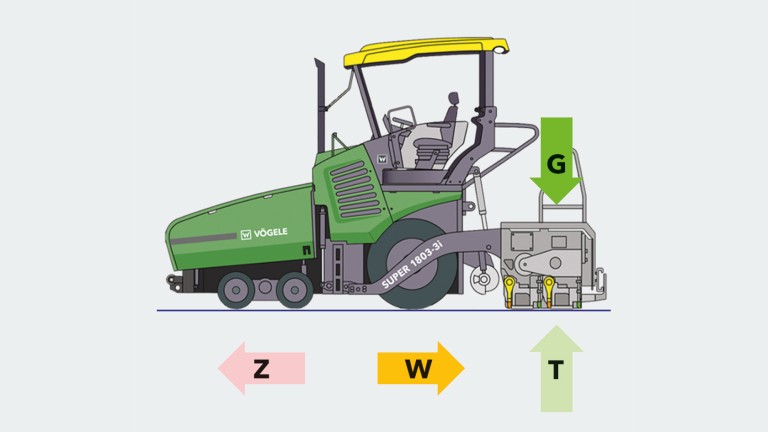
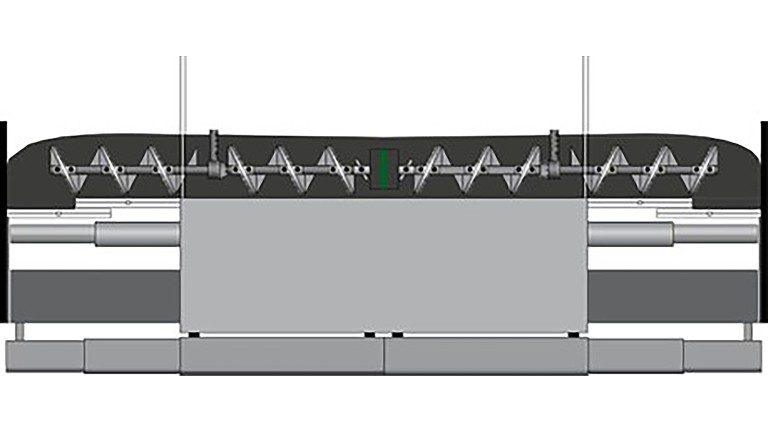
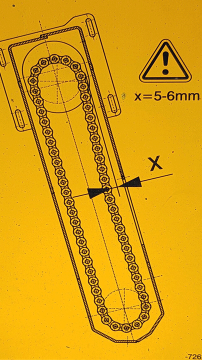
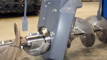
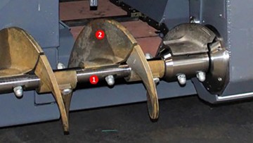
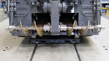
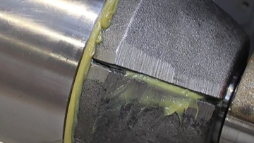
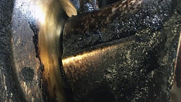
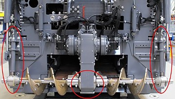
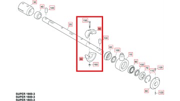
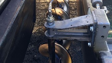
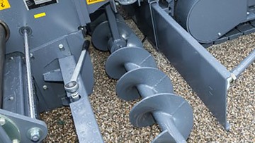
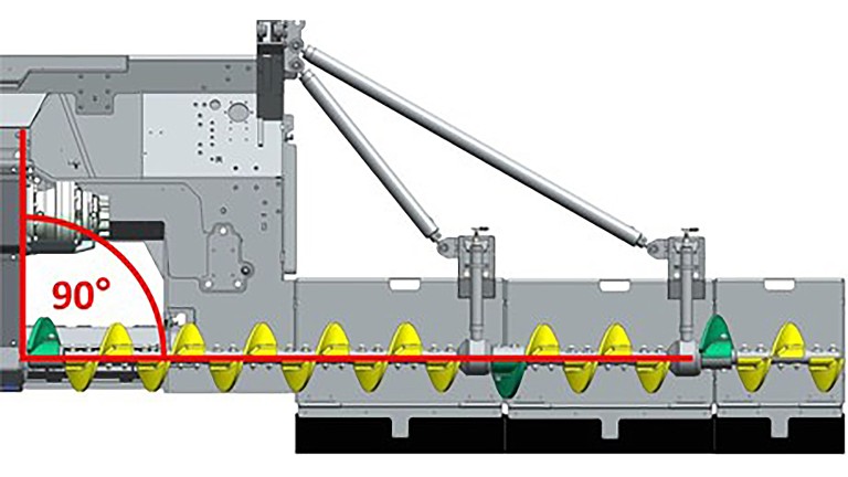
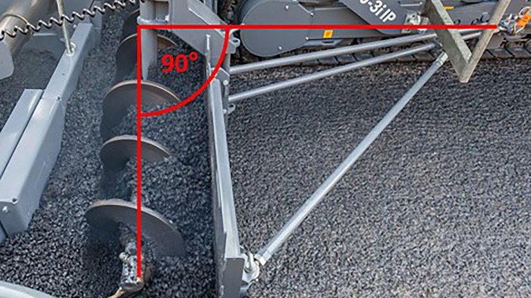
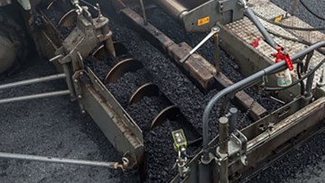
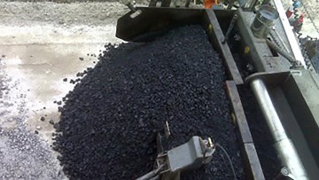
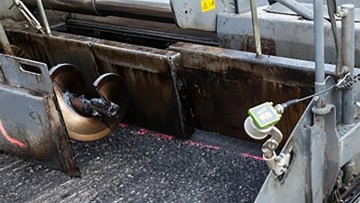
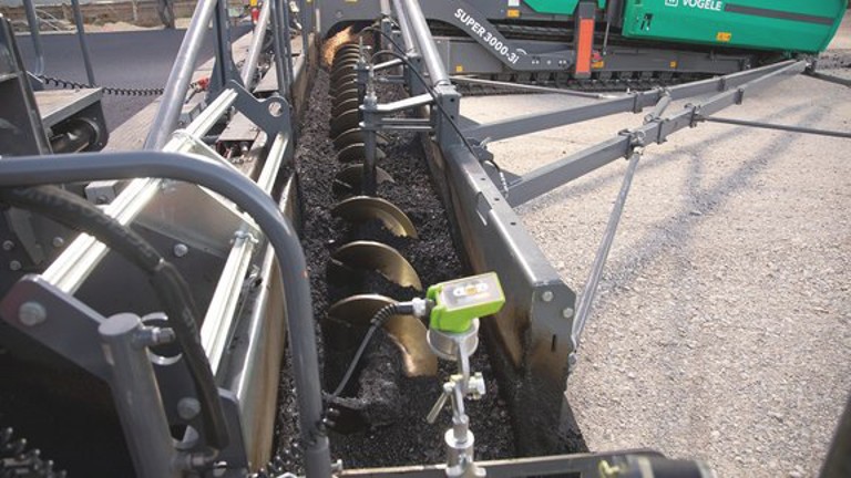
Spreading augers

VÖGELE spreading augers

The spreading auger spreads the material transported by the conveyor chains in front of the screed. The amount of material in front of the screed has a major influence on the equilibrium of forces on the screed, and, in return, on its floating behaviour.

The more material there is in front of the screed and the higher the resistance (R) to the tractive power (T), the greater the tendency of the screed to float. In contrast, if the mix feed rate is low and the resistance (R) is less, the screed will drop.

The screed weight (SW) and the load bearing capacity (LBC) of the material do not affect material conveying.

A constant, even supply of material during paving is therefore essential for good paving results! To achieve this, longitudinal material conveying and lateral spreading must be ideally coordinated.

Basic components
  • Hydraulic cylinder height adjustment
  • Hydraulic motor
  • Auger shaft
  • Bearing blocks
Additional components
  • Auger extensions
  • Limiting plates for the auger tunnel
  • Deflectors
  • Horizontal and vertical supports

Basic components

Hydraulic cylinder height adjustment
Hydraulic motor for the auger drive
Auger shaft
Bearing blocks
Hydraulic cylinder height adjustment

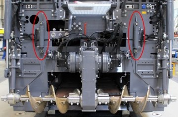
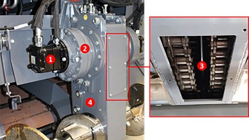
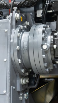
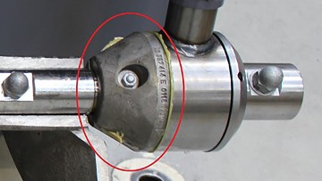
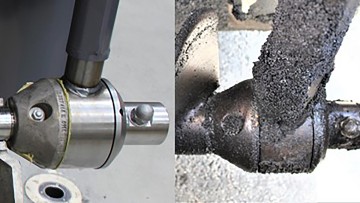
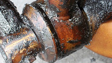
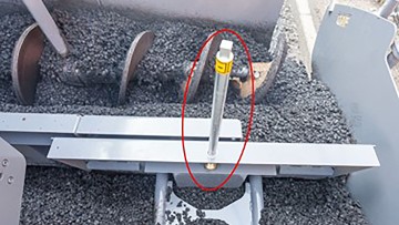
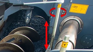
On all VÖGELE SUPER series pavers, the hydraulic cylinder allows the entire centre auger bearing box to be raised or lowered by 15 cm to enable correct adjustment to the desired paving thickness.

Hydraulic motor

The hydraulic motor (1) drives the drive chain (3) in the chain case (4) via the gearbox (2).

Auger wear check

Due to their constant contact with the paving mix, and the resulting abrasion, some auger components are inevitably susceptible to wear. To prevent impairment or failure of mix spreading, the following parts must be checked regularly and replaced whenever necessary:

Drive chain tension

In the example here, we show you how to adjust the tension of the drive chains on a SUPER 1800-3. You can find this information for other paver models in the relevant instruction manuals. Please pay close attention to the warnings and safety instructions.

Unscrew the bolts of the cover plate and remove it.

Check the chain tension in the measuring area under the cover plate: The drive chain should be manually movable by a maximum of 5 – 6 mm

Unscrew the four fastening screws on the bracket, but do not remove them completely.

Lock nut
Setting screw

Release the counter nut and turn the setting screw until the correct chain tension is achieved:

  • Turn the setting screw clockwise to increase the chain tension.
  • Turn the setting screw anti-clockwise to reduce the chain tension.

When the tension is set correctly, re-tighten the counter nut and the bracket fastening screws. You can refit the cover plate when both the left and right side drive chains have been checked and correctly adjusted.

Insufficiently tensioned drive chains can cause the spreading auger to start jerking. This has a negative impact on the floating behaviour of the screed. Furthermore, chains that are too loosely tensioned significantly increase wear and can lead to a total failure.

Chain case guard

The front and the underside of the chain case are particularly susceptible to heavy wearing through direct contact with the mix. An exchangeable guard is mounted on its front to prevent wearing and the eventual need for replacement of the entire chain case.

Replace the guard as soon as it is worn to prevent damage to the chain case and the drive unit.

Auger shaft

The auger shaft (1) is driven by the drive chain. The auger blades (2) are mounted on the shaft. There are different auger blades for the left and right sides to convey the material outwards.

1 = auger shaft 2 = auger blade

The two sides are controlled separately and can also be reversed.

Auger wear check

Due to their constant contact with the paving mix, and the resulting abrasion, some auger components are inevitably susceptible to wear. To prevent impairment or failure of mix spreading, the following parts must be checked regularly and replaced whenever necessary:

Auger blades

Abrasion causes a gradual decrease of the web width of the auger blade that results in it becoming pointed and sharp-edged.

Comparison of new (left) and worn (right) auger blades

New
Worn

As wear progresses, the diameter becomes smaller and smaller, which increases the risk of the auger blade breaking off. This has a negative effect on the flow of the asphalt mix and could reduce paving performance to a minimum.

Auger gear oil

The gear oil for the left and right side drive units must be checked every 500 operating hours and should be changed at intervals of 1,000 hours.

Draining gear oil:

  • Open the filler port
  • Remove the oil drain plug
  • Drain used oil completely
  • Insert the oil drain plug with a new seal ring and tighten
  • Dispose of used oil in an environmentally friendly way

Filling gear oil:

  • Remove the oil level checking screw
  • Pour in new gear oil via the filler port until oil begins to overflow out of the threaded hole for the oil level checking screw
  • Close the filler port
  • Insert the oil level checking screw with a new seal ring and tighten

Oil level checking screw
Oil drain plug

Drive chain checking

The tension of the drive chains must be checked and adjusted if necessary every 500 operating hours.


Cleaning

All machine parts that come into contact with the mix must be cleaned after every paving job. To do so, spray the auger, among other items, with cleaning agent before the last material feed.

When paving is finished, first clean the parts that cool down quickly, such as the centre auger bearing box, the deflectors and the auger tunnel limiting plates.

Activate the cleaning function, and let it run for a few minutes As the central lubrication system is also active during this time, any mix residues that may have penetrated into the bearings will be pressed out by the grease.

‘Heating/Cleaning function’ button

Also regularly check the bolt connections of the auger blades and tighten them if necessary (switch the diesel engine OFF!).

Observe all safety regulations!

Switch the diesel engine OFF and secure it against being switched back on every time you need to work in the auger feed area.

We offer tailored service packages for the different paver types to ensure that you are ideally prepared for the quick replacement of individual parts or the entire auger unit.

Service package for auger blades | Service package for spreading augers
Bearing blocks

The auger shafts are mounted on bearings in the middle in the chain case and on bearing blocks at the sides.

Lubrication of bearings

The bearings for longitudinal mix conveying and lateral spreading are lubricated by the central lubrication system. As soon as at least one of the material conveyors (conveyor chains or augers) is running, the grease is automatically pumped from the grease pump to the individual bearings via a progressive grease distributor.

Electric grease pump with reservoir and safety valve

Progressive grease distributor with lubricant lines to the individual bearings

Example: outer auger shaft bearing

The filling level of the reservoir must be checked daily prior to each paving job and refilled as necessary with high-temperature grease (refer to the instruction manual for specifications).

Manual lubrication of bearings

If one of the lubrication system components is defective, the bearings can also be manually lubricated via grease nipples.

Bearings

Two half-shell clamping pieces are fitted next to the bearing blocks to protect them against excessive abrasion. Replacing the clamping pieces is much quicker, easier and cheaper than replacing the complete bearing blocks. Check the clamping pieces and, if necessary, replace them before damage to the bearing blocks can occur.

Also, excessive bearing play can cause mix to penetrate into the bearing block, and the bearings can seize up. The radial bearing play can be checked using a long tyre lever.

A failure of mix spreading would be the same as a total machine outage. To prevent this, check the bearings regularly, and replace them in good time.

Additional components

Even when paving at large widths, the asphalt mix can be conveyed optimally to the outer edges of the screed by means of auger extensions, auger tunnel limiting plates and deflectors.

Deflectors
Limiting plates for the auger tunnel
Auger extensions
Auger extensions

For larger paving widths, the auger extensions (comprising the shaft and bolt-on blades) are supported by additional bearing blocks.

Short extensions can also be installed without the need for additional bearings. In this example the auger blades are also welded directly onto the shaft.

Correct settings

For larger paving widths, the auger extensions must be correctly aligned and stabilised with the aid of the vertical and horizontal supports. Incorrectly adjusted supports can place heavy loads on the drive unit and the auger bearings and thus increase wear on these components.

The vertical supports are used to align the auger at an angle of 90° to the chain case and ensure that it does not sag or bend upwards along its entire length.

The horizontal supports are adjusted to ensure that the auger extensions are at a 90° angle to the undercarriage/chassis. The ‘Setup and modification’ chapters of the paver and screed instruction manuals provide installation instructions and lists of the parts required for different working widths.

For very large working widths, blades with a larger diameter are mounted on the inside of the spreading auger than on the outside. This results in a more even material flow.

Lubrication of auger extensions

If bearing-mounted auger extensions are fitted, they must of course be lubricated as well. The connections for the grease lines are located on the sides of the paver's rear bulkhead.

Without bearing-mounted auger extensions, the pressure and return (R) connections must be interconnected (as shown in the picture above).

Pressure connection
Return connection

This connecting line must be removed in the case of bearing-mounted auger extensions. The grease line to the auger extension bearing block is attached to the pressure connection, and the return connection (R) is closed off by a blanking plug.

Limiting plates for the auger tunnel

The auger tunnel limiting plates ensure that the mix is guided evenly to the edge and does not roll away to the front. This also minimises the risk of the paving material being segregated.

With limiting plates

Insufficiently wide auger tunnel limiting plate configuration

Deflectors

The deflectors help to ensure controlled feeding of the mix into the outer paving area. The deflectors also considerably reduce the amount of mix feed in front of the hydraulic extensions.

The amount of material in front of the screed's hydraulic extensions can be controlled by manually adjusting the height of the deflectors via the spindle.

Horizontal and vertical supports

The horizontal and vertical supports align and stabilise the auger extensions and auger tunnel limiting plates.

DANGER! RISK OF BEING DRAWN INTO THE MACHINE!

Contact with rotating augers can lead to serious or fatal injuries! Always maintain a safe distance from moving parts! When working on the auger, switch off the drive motor and secure it against being unintentionally switched back on.

VÖGELE feed of mix

Order and buy original parts for VÖGELE feed of mix online.

Go to VÖGELE feed of mix
Find out more Material conveying
Return to overview