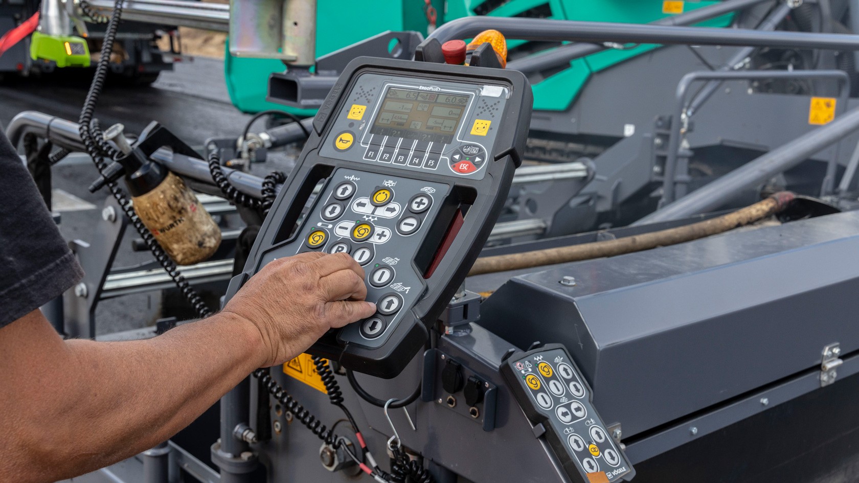
Basic screed adjustments

Correct adjustment of the screed before paving begins prevents unnecessary wear.

Click on the gallery to see the procedures for the various screed components.

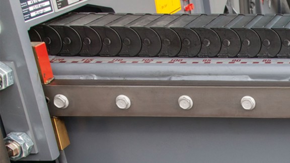
Setting the planing angle of the extending screed

The planing angle must be correctly set on both the inner and outer edges of the extending screed.

Setting the outer planing angle on the extending screed:
  • Retract the screed to its maximum extent.
  • Lay a ruler (4) under the screed plates at the height of the outer adjusting spindle.
  • Adjust the height of the screed extension so that the ruler lies on the points (1), (2) and (3).
  • Measure the gap: There must be a gap of approximately 1 mm between the ruler and the screed plates at a position around 30 mm behind the rear edge of the tamper.
  • Release the chains on the adjusting spindles.
  • Make the adjustments on the front adjusting spindle with appropriate tools.
  • Measure the gap and, if necessary, repeat the adjustment procedure.
Show more Show less
Setting the inner planing angle on the extending screed:
  • Extend the screed until the adjusting spindles are directly beneath the sliding blocks.
  • From here, repeat the adjustment procedure as before, from the second step of the setting procedure for the outer planing angle.
Show more Show less

After setting the planing angle, please tighten the clamping screw for height adjustment again. Now check the settings again.
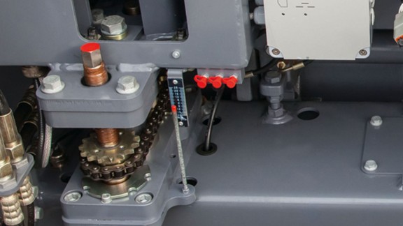

Adjusting spindles

Before carrying out the adjustment of the adjusting spindle, the play of the threaded bush (5) should be checked with tightened locking nuts.

Height adjustment of the adjusting spindle:
  • Set the screed with extension units on wooden blocks.
  • Release the chain (1) with the aid of the shackle.
  • Turn the adjusting spindle (2) down so that the front face (3) comes to rest completely on the flange face on the screed frame.
  • Remove the internal hex bolt (4) from the flange.
  • Hand-tighten the threaded bush (5) with a suitable tool.
  • Remove the threaded bush (5) with a 45° twist to expose the hole for the locking bolt.
  • Tighten the internal hex bolt (4).
Show more Show less

Always adjust all four spindles of each extending screed.
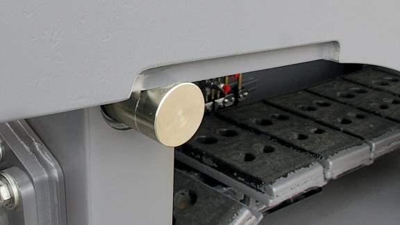
Tampers

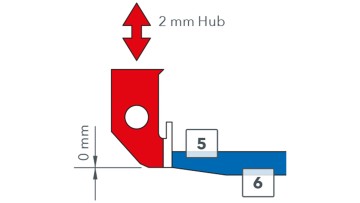
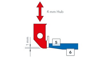
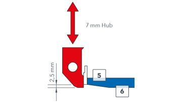
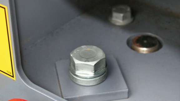
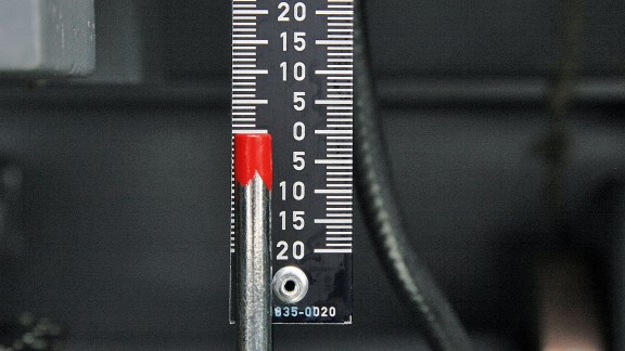
The tamper must always have the same stroke across the entire paving width. The stroke can be altered by twisting the eccentric bush on the drive shaft of the tamper. This can be carried out easily from behind when the paver is being moved from one section to the next. In contrast, adjusting the lower reversal point of the tamper bar in relation to the screed plate, takes a little more time and effort. First of all, the metering gates must be removed to access the bolts that need to be removed from all the shaft mounting brackets. After removal of the locking nut (2), the tamper height can be altered with the bolt (1). The height to be set depends on the stroke setting of the tamper.

(1) Bolt
(2) Locking nut
(3) Eccentric shaft at the lower reversal point
(4) Tamper
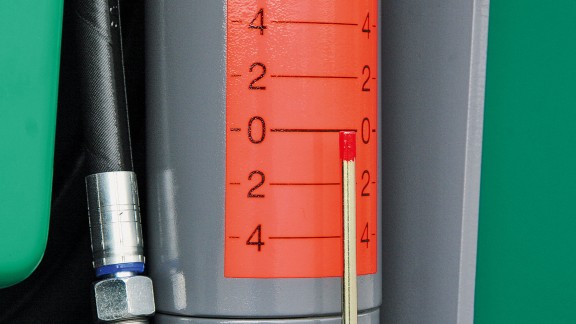
(7) 1 mm at 4 mm stroke
(5) Chamfer
(6) Screed plate

The tamper should be set flush with the screed plate at a stroke of 2 mm (manual check by touch).

Tamper stroke 2 mm

The tamper is flush with the screed plate at the lower reversal point.

Tamper stroke 4 mm

The tamper is positioned at a maximum of 1 mm lower than the chamfer at the lower reversal point.

Tamper stroke 7 mm

The tamper position is 2.5 mm lower than the chamfer at the lower reversal point.

Setting up the pressure bars
  • Remove the twist lock (3) secured nut (2) from the pressure bar cylinder (1).
  • Turn the pressure bar cylinder (1) to adjust the height of the pressure bar(s). The clearance (7) between the pressure bar(s) and bottom edge of the screed plate should be at least 4 mm.
  • Check that the pressure bar cylinder makes contact with the metal plate (5) when retracted.
  • Set the pre-tensioning of the spring (6) to 5.5 mm with the nut (4). This sets the offset (8) to 59.5 mm.
  • Secure the pressure bar cylinder (3) again.
Show more Show less
Screed metering gate

The tamper (3) must be set to rest lightly over the entire length of the wear strip (1). Then adjust the spring steel bar (2) on the metering gate by means of the screw (4) from the rear of the screed until there is a gap of 0.5 to 1 mm between the tamper and the spring steel bar. By removing screws (6) and fitting various small shims (5), the metering gate should be aligned so that the spring steel bar (2) is at least parallel to the tamper or is preferably slightly inclined towards the front.

Finally, recheck the gap between the tamper and the spring steel bar and correct it if necessary.

Mechanical hydraulic side plates

Screed side plate height adjustment is a function often used during the paving process. As a user, you know from experience that this function is often needed when paving, for instance, along kerbs with high or low kerbstones or along gutters.

How side plates help to ensure perfect paving quality:

  • By preventing lateral spread of the mix during paving.
  • By producing clean joints and pavement edges.
  • By ensuring optimal compaction, also at the outer edges of the pavement.
Show more Show less
VÖGELE screeds

Order and buy genuine long-life parts for VÖGELE screeds online now.

> VÖGELE screeds
Back to the Parts Guide
To the Parts Guide